
Process Engineering Company
PLC Power Supply Sizing: How to Estimate I/O Power Requirements
July 30, 2026 Welcome
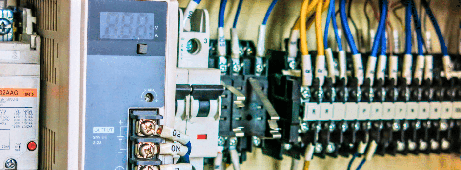
Choosing a PLC power supply is not simply a matter of picking a 24VDC unit and hoping it has enough capacity. The power supply has to support the PLC CPU, communication cards, digital and analog I/O modules, and in many panels, field devices that also run on 24VDC. If the supply is undersized, the control system may not operate reliably. Even if the supply is large enough for today’s load, sizing it too close to the minimum leaves little room for future expansion.
That is why PLC power supply sizing usually starts with a current draw estimate. By adding up the expected load of the controller, I/O, and other connected devices, engineers and panel builders can select a supply with enough capacity for normal operation and a reasonable design margin.
What to Include When Sizing a PLC Power Supply
One of the easiest mistakes in PLC power supply sizing is focusing only on the controller and forgetting everything else in the panel. A 24VDC control power system may need to support several different types of loads, including:
- PLC CPU, base, or rack power: The controller itself has a published current or power requirement that needs to be included in the total.
- Communication modules: Ethernet/IP modules, Modbus TCP cards, serial communication modules, and remote I/O adapters all add to the 24VDC load.
- Digital input modules: Input cards consume current for module electronics and internal circuitry.
- Digital output modules: Output cards have their own current draw, but they may also switch field devices powered by the same 24VDC supply. If so, those field loads need to be included too.
- Analog input and analog output modules: Analog cards often draw more current than simple digital input cards, so it helps to treat them separately during the estimate.
- Other 24VDC devices in the panel: Relays, pressure transmitters, proximity sensors, photoeyes, stack lights, HMIs, industrial switches, and similar accessories may all be part of the same power supply load.
In some control panels, the PLC electronics and field devices share one 24VDC supply. In others, they are separated. Before doing the calculation, it helps to define exactly which devices are being powered by the supply you are sizing.
How to Calculate PLC Power Supply Requirements
The basic idea is straightforward: add up the current draw of every device powered by the 24VDC control power system, then add spare capacity.
A practical formula looks like this:
Total required 24VDC current =
PLC CPU/base current
+ communication module current
+ digital I/O module current
+ analog I/O module current
+ current for any field devices powered from the same supply
Once the total expected load is known, apply a design margin:
Recommended PLC power supply size = Total required current × safety factor
If a 20% spare capacity target is used, the safety factor is 1.25.
For a manual estimate, the process usually looks like this:
- List every 24VDC load powered by the supply.
- Pull the current draw for each device from the manufacturer’s data sheet.
- Add all steady-state current values together.
- Add a safety margin.
- Select the next practical power supply size rather than sizing right at the minimum.
If a component’s power is listed in watts instead of amps, you can convert it using:
Current (A) = Power (W) ÷ Voltage (V)
For example, a 12-watt device on a 24VDC system draws:
12 W ÷ 24 V = 0.5 A
Example PLC Power Supply Calculation
Assume a control panel includes the following 24VDC loads:
- PLC CPU/base: 0.80 A
- two digital input modules at 0.10 A each
- two digital output modules at 0.15 A each
- one analog input module at 0.20 A
- one analog output module at 0.20 A
- one communication module at 0.25 A
- field transmitters and relays powered from the same supply: 1.10 A
Only include field devices that are actually powered by the 24VDC supply being sized. For example, loop-powered 4-20 mA transmitters supplied by another source should not be counted.
Step 1: Add the loads
PLC CPU/base = 0.80 A
Digital input modules = 0.20 A
Digital output modules = 0.30 A
Analog input module = 0.20 A
Analog output module = 0.20 A
Communication module = 0.25 A
Field devices = 1.10 A
Total required current = 3.05 A
Step 2: Add 20% spare capacity
3.05 A × 1.25 = 3.81 A
Step 3: Select the next standard PLC power supply size
A practical recommendation would be a 24VDC, 5A power supply. That leaves room for small additions later and avoids running the supply right at the calculated minimum.
Real-World Factors That Affect PLC Power Supply Sizing
T he example above provides a good starting point for estimating PLC power supply requirements, but several real-world factors can affect the final selection.
Ambient Temperature and Power Supply Derating
A power supply’s rated current is measured under controlled conditions, typically around 25°C (77°F). What matters in practice is the temperature inside the enclosure, which in a closed cabinet can run 15°C to 25°C higher than the surrounding air. Many industrial 24VDC power supplies deliver their full output up to a specified temperature, often around 55°C (131°F), before output begins to derate. Always size against the manufacturer’s published derating curve rather than relying only on the nameplate rating.
For example, a 5A power supply selected for a calculated 3.81A load may appear to have adequate capacity. However, if the enclosure reaches higher operating temperatures, the supply’s usable output can decrease enough to significantly reduce that margin. Size the power supply using the derated output at the expected worst-case enclosure temperature rather than the rated output alone.
Other Design Considerations
When selecting a PLC power supply, also consider:
- Inrush and startup current: Capacitive and inductive loads can draw more current during startup than during normal operation.
- Peak versus steady-state current: Relay and solenoid pull-in current, along with switched inductive loads, may temporarily exceed their normal holding current.
- Continuous loading: Operating a power supply at approximately 50% to 70% of its rated capacity can help extend component life. This design consideration is separate from allowing room for future expansion.
- Protection and redundancy: Critical control systems may use DC-side fusing, redundant power supplies, or redundancy modules to improve system reliability.
Example: Sizing an Allen-Bradley® ControlLogix® System
Allen-Bradley ControlLogix systems work differently than a typical 24VDC control panel. The 1756 modules draw power from the chassis backplane rather than directly from the external 24VDC bus. The chassis power supply powers that backplane, while the 24VDC control power supply supports field devices, relays, transmitters, and HMIs. If a DC chassis power supply is used, it also becomes another load on the 24VDC control power system. Field current, such as 4-20 mA transmitters and solenoids, is counted in the 24VDC bus calculation rather than the backplane total.
When sizing a ControlLogix system, there are two separate calculations:
- Size the chassis power supply by adding the backplane current requirements of every module installed in the chassis. The 5.1V rail is typically the limiting factor.
- Size the 24VDC control power supply by adding the current draw of field devices, relays, transmitters, HMIs, and any DC-powered chassis supplies connected to the 24VDC bus.
Example ControlLogix Backplane Current Requirements
The simplified example below illustrates how backplane current can be totaled when sizing a ControlLogix chassis power supply. Always verify current requirements using the exact modules specified for your project.
| ControlLogix Component | Typical Backplane Current (5.1V) |
| CPU (Controller) | 1.20 A |
| Digital Input Module (16-point) | 0.09 A |
| Digital Output Module (16-point) | 0.28 A |
| Analog Input Module (8-channel) | 0.25 A |
| Analog Output Module (8-channel) | 0.30 A |
| Ethernet Communication Module | 0.56 A |
| ControlNet Communication Module | 0.90 A |
Example Total Backplane Current
| Component | Qty. | Current Each | Total |
| CPU | 1 | 1.20 A | 1.20 A |
| Ethernet Module | 1 | 0.56 A | 0.56 A |
| Digital Input Module | 2 | 0.09 A | 0.18 A |
| Digital Output Module | 2 | 0.28 A | 0.56 A |
| Analog Input Module | 1 | 0.25 A | 0.25 A |
| Total Required Backplane Current | 2.75 A |
Example values shown for illustration. Always verify module current requirements using the manufacturer’s documentation for the exact hardware being used.
Common PLC Power Supply Sizing Mistakes
A manual estimate is useful, but a few common mistakes can still throw off the result:
- Counting only the PLC modules: Relays, transmitters, HMIs, and other accessories on the same 24VDC rail can easily be missed.
- Treating all I/O modules the same: Analog cards, communication modules, and specialty I/O often draw more current than simple digital input cards.
- Ignoring output load current: A digital output module may be switching devices powered from the same supply. Those field loads need to be counted too.
- Leaving no room for expansion: If the supply is selected only for the exact load shown on today’s drawings, there may be no room for a later change.
A quick PLC power supply calculation is a good starting point, but final selection should still be checked against the actual module data sheets and device specifications for the hardware being used.
Need Help Sizing a PLC Power Supply or Designing a Control Panel?
IFS/DXP provides engineered systems and application-specific solutions for industrial automation, control panel integration, and process control projects. If you need help estimating PLC power requirements, selecting a control panel power supply, or building a system around your process requirements, our team can help.