
Engineered to Order, Process Engineering Company
Control Panel Heat Dissipation: How to Calculate Enclosure Cooling Requirements
August 21, 2026 Welcome
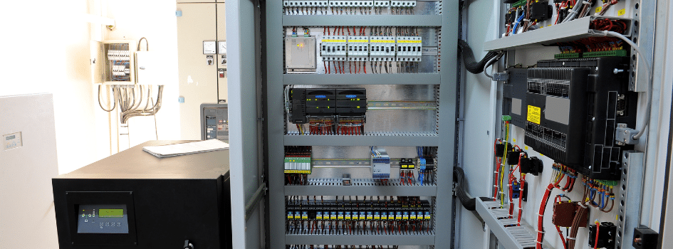
PLCs, power supplies, variable frequency drives (VFDs), transformers, and other components release heat inside a control panel. If the enclosure cannot release enough of that heat, the internal temperature rises and components may trip, age faster, or fail. The calculation below estimates the cooling capacity needed to keep the panel within its temperature limit.
Information Needed for an Enclosure Cooling Calculation
- Enclosure dimensions and mounting arrangement
- Maximum ambient temperature at the panel location
- Maximum desired internal enclosure temperature
- Heat loss from all energized components, in watts
- Enclosure material and its heat-transfer coefficient
- Direct solar exposure, if applicable
Use the highest temperature expected at the panel, not the average room temperature. A panel near process equipment, outdoors, or in a poorly ventilated area may run much hotter.
Set the maximum desired internal temperature from the most temperature-sensitive component, not from a general comfort figure. Most PLCs and VFDs are rated for a maximum ambient of 40–50°C and begin derating above it, so the lowest-rated component in the panel usually sets the internal limit. Choosing a target above that rating shortens component life even when the enclosure calculation still “passes.”
Step 1: Calculate the Internal Component Heat Load
Add the published heat loss for every energized component, including PLCs, VFDs, power supplies, transformers, relays, contactors, and communication equipment:
Qᵥ = Q₁ + Q₂ + Q₃ + …
Use each manufacturer’s published power-loss value at the expected load. Do not use the full electrical input rating unless all of that power becomes heat inside the enclosure. If only efficiency is published, use:
Heat loss (W) = input power (W) × [1 − efficiency]
VFD losses change with motor load, carrier frequency, and operating conditions. Manufacturer data is better than a broad rule of thumb here.
Step 2: Calculate Estimated Cooling Capacity
Heat moves through the enclosure walls when the internal and ambient temperatures differ. When the target internal temperature is above ambient, the surface may remove part of the component heat load:
Qₛ = A × k × ΔT
- Qₛ = heat transferred through the enclosure surface, in watts
- A = effective exposed surface area, in square meters
- k = enclosure heat-transfer coefficient, in W/m²·K
- ΔT = internal target temperature minus ambient temperature, in °C or K
Effective surface area is not always all six sides. The method in IEC 60890 assigns a surface factor based on how the enclosure is installed: a freestanding cabinet exposed on all sides has more effective area than one mounted against a wall, wedged between adjacent cabinets, or recessed into an alcove. Rittal and Pfannenberg publish surface-area factors derived from this standard for each mounting arrangement—use them rather than assuming all six sides are active.
The coefficient k combines convection and radiation into a single overall heat-transfer value, which is why it is specific to both the enclosure material and the surrounding air condition. Typical values in static indoor air:
- Painted sheet steel: 5.5 W/m²·K
- Stainless steel: ~4.5 W/m²·K
- Aluminum: ~12 W/m²·K
- Polyester / GRP (fiberglass): ~3.5 W/m²·K
Confirm the value against the enclosure manufacturer’s data for your material and mounting.
When the desired internal temperature is higher than ambient, subtract the heat that can leave through the enclosure surface:
Estimated cooling capacity (W) = internal heat load − enclosure surface heat loss
If ambient temperature is higher than the desired internal temperature, add the surface heat gain instead. Add solar load too if the panel is exposed to sunlight.
Convert watts to BTU/hr with:
Cooling capacity (BTU/hr) = cooling capacity (W) × 3.412
Control Panel Cooling Calculation Example
Assume a wall-mounted painted sheet-steel enclosure has an effective exposed surface area of 3.6 m². The components release 600 W of heat. Maximum ambient temperature is 95°F (35°C), and the desired internal temperature is 104°F (40°C). The temperature difference is 9°F, or 5 K.
Enclosure surface heat loss = 3.6 m² × 5.5 W/m²·K × 5 K = 99 W
Estimated cooling capacity = 600 W − 99 W = 501 W
501 W × 3.412 = approximately 1,710 BTU/hr
The enclosure still needs to remove about 501 W, or 1,710 BTU/hr. Check the selected unit’s rated capacity at the application’s maximum ambient temperature.
Direct sunlight, nearby heat sources, altitude, blocked internal airflow, dirty filters, and future panel expansion can change the result. Check for hot spots near VFDs, power supplies, and transformers too.
Size the cooling equipment with margin above the calculated load. A common practice is to add 10–20%, or simply select the next standard unit size up, to cover manufacturing tolerances, filter loading, component aging, and future additions to the panel. Do not size exactly to the calculated number.
Natural Convection, Fan, or Enclosure Air Conditioner?
Natural Heat Dissipation
Natural heat loss may be enough when the component load is low, ambient air stays below the internal limit, and enough enclosure surface is exposed. A larger enclosure or more space around it may help.
Filtered Fan Ventilation
A fan can move cooler ambient air through the enclosure when natural heat loss is not enough. It cannot cool below ambient temperature. Filters may be needed, but they reduce airflow as they load with dust. Outside air may also conflict with the required enclosure rating.
Size the fan from the heat to be removed and the allowable temperature rise between incoming ambient air and the internal target:
V = f × Qᵥ / ΔT
- V = required airflow, in m³/h
- f = air constant, ≈ 3.1 m³·K/(W·h) at sea level
- Qᵥ = heat to be removed, in watts
- ΔT = internal target temperature minus ambient temperature, in K
For the 600 W case at a 5 K rise, the fan would need to move roughly 3.1 × 600 / 5 ≈ 372 m³/h (about 219 CFM) of filtered air, before accounting for filter loading and back-pressure. The constant f increases with altitude, because thinner air carries less heat per unit volume, so airflow requirements rise at elevation. Note that required airflow grows as the allowable temperature difference shrinks—tight internal targets push fan size up quickly, which is one reason a small ΔT often points toward closed-loop cooling instead.
Closed-Loop Cooling
An enclosure air conditioner or another closed-loop system may be needed when ambient air is too warm, the enclosure must stay sealed, or dust, moisture, and corrosive contaminants rule out open ventilation. Rated cooling output changes with ambient conditions, so check the manufacturer’s performance data.
Condensation, Humidity, and Cold Environments
Cooling is only half of enclosure climate control. Outdoor and unconditioned panels (NEMA 3R, 4, and 4X) also have to manage moisture and low temperatures:
- Condensation. When a sealed enclosure cools below the dew point of the trapped air, moisture forms on internal surfaces and components. An enclosure air conditioner should not drive the interior below the dew point, and its condensate must drain freely away from live parts.
- Anti-condensation heating. A small enclosure heater controlled by a hygrostat (humidity switch) or thermostat keeps internal surfaces above the dew point in cold or humid locations. This is common on outdoor pump-control and instrumentation panels.
- Sealed vs. ventilated trade-off. Filtered ventilation draws in outside humidity and contaminants along with cooler air. Where moisture, dust, or corrosives are a concern, a sealed enclosure with closed-loop cooling and a heater is usually a better climate strategy than open ventilation.
Sizing the heater follows the surface-loss idea in reverse: the heater must replace the heat lost through the walls at the coldest expected ambient, plus a margin to stay above the dew point.
Control Panel Engineering from IFS/DXP
IFS/DXP designs and integrates control panels for engineered systems and application-specific process packages. Contact us to discuss control panels and automation for your application.