
Process Engineering Company
What is Turndown Ratio in Process Equipment?
October 22, 2026 Welcome
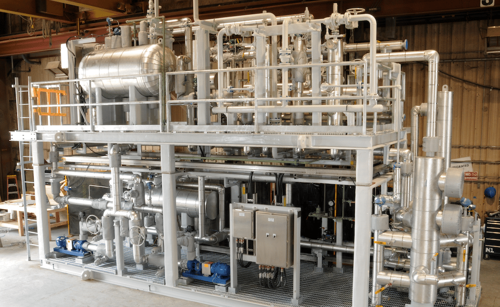
Turndown ratio compares equipment’s maximum capacity with its minimum usable capacity under specified conditions. A 10:1 turndown ratio means the minimum is one-tenth of the maximum. That capacity might be flow rate or heat output, depending on the equipment. The useful question is how far demand can drop while the equipment still meets the process requirements.
Turndown Ratio and Operating Range
Equipment selected for peak production also needs to work when production slows. A system might handle 100 GPM at full demand but spend much of its time running at 20 GPM.
The minimum usable capacity is not the lowest point at which equipment remains running. It is the lowest point at which it meets the required accuracy, control, or other performance criteria. Those limits need to be stated with the ratio.
For example, 10:1 turndown corresponds to a minimum of 10% of maximum capacity. It does not mean continuous operation down to zero.
How to Calculate Turndown Ratio
Turndown ratio = Maximum usable capacity ÷ Minimum usable capacity
For a hypothetical flow meter with a specified operating range of 10-100 GPM:
100 GPM ÷ 10 GPM = 10:1
You can also calculate the minimum capacity:
Minimum usable capacity = Maximum usable capacity ÷ Turndown ratio
A 100 GPM maximum with 5:1 turndown gives a 20 GPM minimum.
Use the same units and operating basis for both values. For gas flow, do not mix actual flow with standard flow. Also, a calculated ratio does not establish equipment capability. The stated range still needs manufacturer data or engineering validation.
Turndown Ratio in Different Types of Equipment
Flow Meter Turndown and Accuracy
A flow meter’s turndown describes its usable measurement range but read the accuracy specification alongside it. The error allowance may change across that range.
Accuracy expressed as a percentage of full scale can represent a larger percentage of the reading at low flow. A meter that detects low flow may still fall short of the measurement performance your process requires.
Control Valve Rangeability vs. Installed Turndown
A control valve’s inherent rangeability describes the range of flow coefficients over which it follows its specified characteristic. That rating does not automatically become the installed system’s turndown.
Available pressure drops changes with operating conditions. Valve sizing, the actuator, and piping resistance also affect control. An oversized valve may handle peak flow but provide poor control near its closed position.
Heater Output vs. Minimum Process Flow
Heat output and process flow are separate limits. Reducing an electric heater’s power does not establish how far fluid flow can fall.
At low flow, heat transfer at the element surface changes. Local temperatures can exceed fluid, or equipment limits even when the outlet temperature appears acceptable. IFS’s electric process heater specification calls for flow turndown and the corresponding film temperature at minimum flow.
How Components Affect Process Skid Turndown
A complete skid must meet its requirements across the requested operating range. One component’s rating cannot establish that range for the package.
Suppose a meter can measure 10-100 GPM, but another component requires at least 25 GPM under the same conditions. The package cannot claim 10:1 turndown based on the meter alone.
Recirculation, staged equipment, or different component selections may extend the usable range. Each approach changes the design, and internal circulation is not the same as flow delivered to the process.
For centrifugal pumps, the pump curve helps evaluate performance across the required flow range, though minimum continuous flow limits also need to be checked.
Is a Higher Turndown Ratio Better?
A higher ratio helps when demand varies enough to require it. It does not automatically mean lower energy use or better performance.
Specify the actual operating range first. Selecting excessive maximum capacity can make low-demand operation harder, even when the equipment has an attractive advertised ratio.
Operating Conditions to Specify Before Equipment Selection
Provide the equipment supplier with:
- Minimum, normal, and maximum flow or load
- Fluid composition, viscosity, and other relevant properties
- Pressure and temperature across operating cases
- Required measurement accuracy and control performance
- Startup conditions and expected changes in demand
Identify which conditions require continuous operation. Startup limits may differ from normal operating limits.
Plan Your Process Operating Range with IFS/DXP
IFS/DXP designs engineered-to-order process systems around application requirements. Contact IFS/DXP with your operating conditions to discuss equipment selection and a usable turndown range for the complete package.